5.0 Test Results and Discussion
5.1 Dimensional Measurements and Interferometer Examinations
The results of the dimensional check showed that the connectors and termini complied with the dimensions and tolerances given by the manufacturer and the associated military specifications (MIL-C-38999 and MIL-T-29504). This leads to the conclusion that the parts being evaluated are physically representative of the parts selected for use on flight hardware.
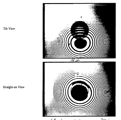
Interferometer measurements were taken for each of the eight fiber end faces to quantify their initial polish quality (shape). The intent was to create a convex shaped fiber end face centered on the fiber core. Theoretically, optical power loss is reduced with a highly concentric polish which leaves no surface discontinuities in the glass (that will cause reflection) such as cracks, pits and material contamination.
An interferometer image appears as a fringe pattern whose center, or "bull's eye" is at the center of the fiber end face polish radius (Figure 4). This "straight-on" view provides quantifiable polish offset data and can show serious damage to the glass such as crushes and large cracks. The interferometer used in this evaluation also employed a tilt function that showed physical characteristics of the fiber polish from a profile view. Known values such as the fiber size and the distance between the fringes are used to calculate the fiber protrusion (distance between highest point on the glass fiber and the highest point of the ceramic ferrule). Table II in Appendix A shows the data taken for the evaluation cable assembly and the acceptance criteria used by XTE and TRMM.
None of the termini polishes complied with all of the established limits, however they were considered acceptable for the needs of the evaluation. Optical time domain reflectometer (OTDR) measurements performed later in the evaluation (after the first vibration test) confirmed that all four of the fibers were making physical contact. No serious defects were found on any of the eight termini although at least one had significantly large chips in the fiber cladding outer diameter.
 Next Section
 Up to TVA Homepage
 Back to the Library