5.4 The First Vibration Test - Thick Bracket
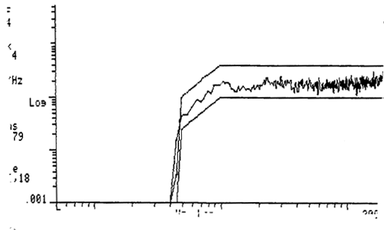
A standard test method qualifying high reliability connectors was used to evaluate the connector's vibration performance. This consisted of a set-up that monitored optical throughput during a random vibration profile which provided 18.79 Grms from 20 to 2000 Hz for six minutes in each of three axes (Figure 9, x-axis was the most dynamic for the mounting bracket used). A bracket made of machined aluminum was configured to provide a fixture that was as "quiet" as possible with respect to its own vibration characteristics. The original bracket proposed in the test plan was found to be highly resonant within the test frequency range and so was not used to establish the qualification data. It was used in a subsequent vibration test described below as supplemental testing. Both brackets are shown in Figure 10.
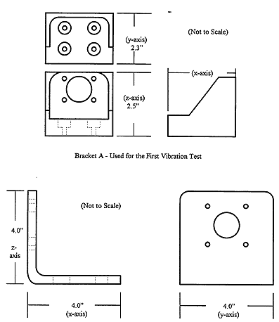
Bracket B - Used for the Second Vibration Test
The optical signal was reduced to 8W (-20.969 dBm), using an optical attenuator, to simulate a signal similar in amplitude to that expected for the actual MIL-STD-1773 application. Optical monitoring was accomplished through the use of optical to electrical converters and a Hewlett Packard 54501A digital oscilloscope driven by external software. Two optical channels were monitored during each test run. To get data for all four channels in the x-direction, the x-axis test was run twice, once monitoring channels 41 and 42 and then monitoring channels 43 and 44. A Tektronics TDS 544 digital oscilloscope was used to view the signal real-time and operated in storage mode to save throughput deviations (in mV) over the duration of the test run.
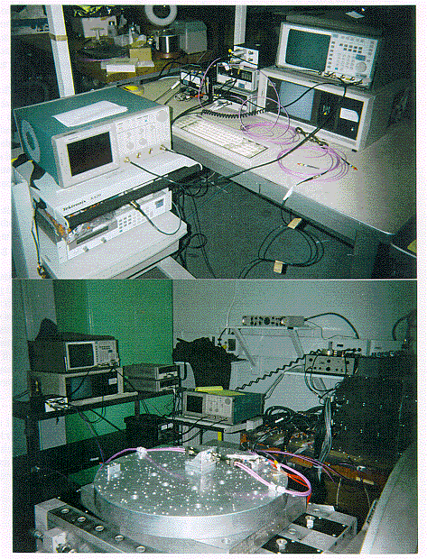
The software monitored the oscilloscope, changing from one channel to the other every five seconds. A trigger was set at a mV level equal to a 0.45 dB reduction in optical signal. When a trigger event occurred, the program would capture the Vmin value from the oscilloscope, tag it with the corresponding channel number and dump it to a data file. It would then switch to the other channel and wait for a similar trigger event. If no event occurred, the program would switch to the next channel after five seconds. At the end of every test, a false trigger event was simulated on each of the channels to verify that the program and scope were still working as intended. The vibration test set-up is shown in Figure 11.
The tests were run in an order which minimized the effects of re-mating the SMA connectors. After the connector was mounted to the bracket, it was torque striped at every coupling ring on the connector and backshell. Inspection after the test did not show any break in the torque striping or other evidence of backing-off on any of the coupling mechanisms.
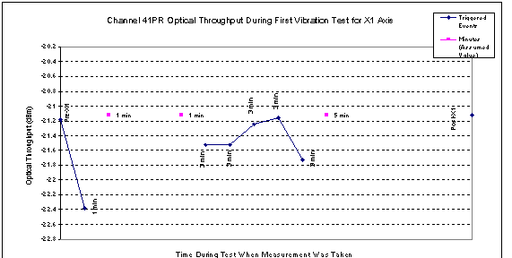
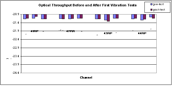
The data taken for this test is given in appendix A. The only trigger events that occurred during testing using the thick bracket were on channel 41 during the first x-axis exposure. Figure 12 shows the optical throughput before the X1 test for channel 41PR, the approximate throughput values at the time of the trigger events and the throughput measured for the channel at the end of the 6 minute test. This data shows that the channel fully recovered after the trigger events while increasing in loss by as much as 1.2 dB during the events. The lack of trigger events for the rest of the five remaining axis runs and the lack of contamination on channel 41 pin and socket suggests that channel 41 physically settled into a stable alignment position due to the application of vibration and that the discontinuities observed in Figure 12 do not necessarily indicate part failure.
Figure 13 shows that after each of the six vibration tests, there were no significant decreases in optical throughput. The data is plotted, pre-test value with post-test value, in the order the channels were tested. Again, to reduce SMA repeatability effects, measurements were not taken for each channel after each axis run, but only for those runs for which they were actively monitored.
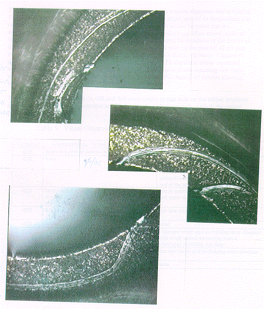
The second part of the vibration test was designed to determine whether the SMA connector ferrules would crush the active device lenses during vibration. The test results showed that the SMA connector ferrules did not affect the active device lenses and that no significant change occurred in throughput for the test cable. Figures 14 and 15 show that one of the two active devices subjected to the mated condition, did exhibit evidence of scratches on the metal package, but not on the glass.
 Next Section
 Up to TVA Homepage
 Back to the Library